Saturn M7

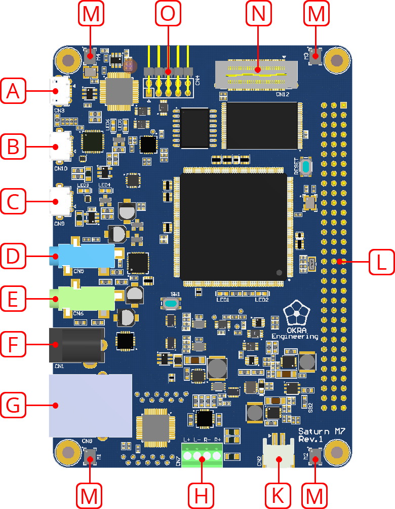
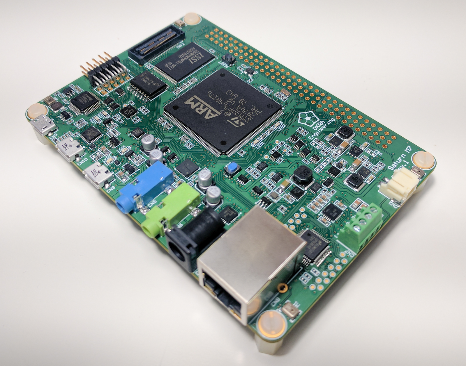
The Saturn M7 is an embedded audio development board designed around a STM32F7 series microcontroller by STMicroelectornics.

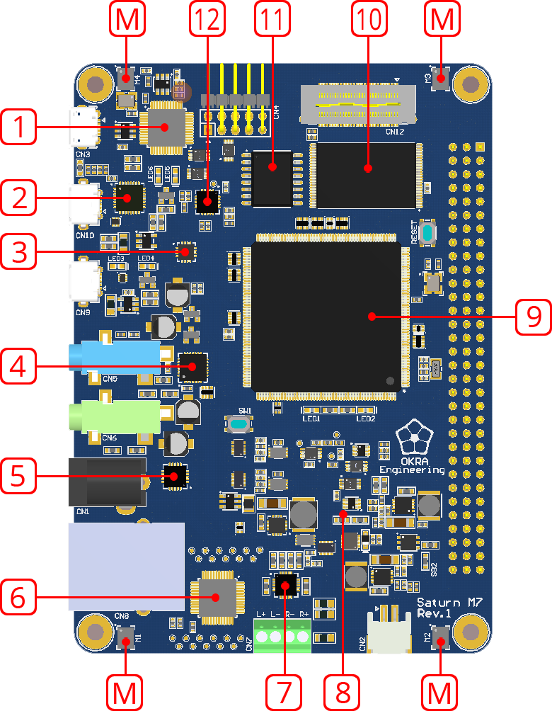
The microcontroller has an ARM® Cortex®-M7 core running at 216Mhz, capable of performing multimedia signal processing tasks while simultaneously managing various communication peripherals.

Saturn M7

The board is designed to expose all the audio related peripherals available on the microcontroller, in addition to all communication peripherlas relevant to controlling the system.

The board has a high performance Delta Sigma CODEC (32bit, 216KHz, 108dB S/N) with 2 channels of input and 2 channels of output. The inputs can be captured at 16, 20, 24, and 32 bit resolution at up to 192KHz, while output resolutions of 16, 24, and 32 bit at 192KHz are supported. The CODEC has high resolution filters for superior audio quality featuring short group delays.

The board also has 4 omni-directional MEMS microphones with an acoustic overload point of 120dB SPL, a 61dB signal-to-noise ratio, and -26dB FS sensitivity. The microphones respond to frequencies between 20Hz and 10KHz. They have a flat response between 100Hz and 5KHz (±1dB).

The board has a stereo class-AB headphone amplifier capable of driving 60mW into a 16 Ohm load. It also has a stereo class-D audio amplifier capable of driving 2.1W per channel into a 4 Ohm load. Both amplifiers are connected to the CODEC’s output.

The board comes with a low jitter, 8 channel configurable clock synthesizer. It drives the audio peripherals and CODEC.

Clocks on multiple Saturn M7 boards can be synchronized down to 8ns over Ethernet through Precision Time Protocol (PTP).

The board has a 60 pin high speed header to interface with a TFT display with touch screen capability over MIPI-DSI. It also has a 96 pin header, which exposes the many digital and analog I/O pins and peripherals of the microcontroller.

The board can be powered over any of the USB ports, through a DC barrel connector, or a lithium-ion battery.

An on-board programmer and debugger is available through a USB interface, which can also be configured as a virtual COM port. The board can also interface with external programmers and debuggers.

Board Features

Function Features
Processer
  • STM32F769 ARM Cortex-M7 running at 216 MHz
  • 2MByte Flash and 512 KByte SRAM
External Memory
  • 16Mbit Asynchronous SRAM with 10ns response time
  • 512Mbit External NOR QUAD SPI Flash
Audio
  • 32-bit / 192KHz / 108dB SNR Stereo input/output CODEC
  • 4x MEMS Microphones
  • Class A/B Headphone Amplifier (80mW into 16 Ohms)
  • Class D Audio Amplifier (2.1W into 4 Ohm @ 5V)
  • x3 Serial Audio Interfaces (SAI) available through the expansion headers 1
  • x4 S/PDIF Transmitters available on the SAI data channels
  • S/PDIF Receiver with x4 input selections over the expansion headers
  • Two half duplex I2S peripherals 2, 3 with a master clock output
Ethernet
  • 10/100 Base-T with Precision Time Protocol
USB
  • x1 High Speed On-The-Go with Sync
  • x1 Full Speed On-The-Go
Clock
  • 8 channel clock generator (up to 200MHz) programmable over I2C
  • Ultra low jitter clock available over expansion
Display / Touch
  • Dual channel MIPI-DSI available through high speed expansion with HDMI support
  • Multi-Touch interface support through I2C
Serial Peripherals
  • x1 SPI port with hardware controlled chip select
  • x3 I2C ports
  • x3 UART ports 4
Programming / Debugging
  • Serial Wire Debug (SWD) over dedicated High Speed USB with Virtual COM Port (VCP)
  • Support for external SWD debugger with Serial Wire Output (SWO) over expansion header
  • DFU programming available over full speed USB port
  • UART programming available over VCP
Power
  • 5V to 15V supply over barrel connector
  • 5V supply over USB ports
  • 3.7V Lithium-Ion battery
  • Power management circuit
  • Low power and sleep modes available
  • External power supply over expansion header possible
Interface
  • x1 red LED
  • x1 green LED
  • x1 user button
  • x1 reset button
Configuration
  • x28 jumpers to re-route signals to support various hardware configurations
  • x13 jumpers to isolate circuit subsections
Dimensions
  • 78mm x 110mm (3.07” x 4.33”)

1. fourth interface is shared with the QUAD SPI peripheral.
2. can also be configured as SPI peripherals with hardware controlled chip select.
3. connected to the CODEC by default, but can be routed to the expansion headers.
4. optional hardware flow control and synchronous clock are available.

Inputs and Outputs

Item Description
A Programming / Debugging | USB Micro-B
B High Speed On-The-Go | USB Micro-AB
C Full Speed On-The-Go | USB Micro-AB
D Stereo Audio Input | 3.5mm Stereo Female
E Stereo Audio Output | 3.5mm Stereo Female
F DC Input 5V to 15V | 5.5mm/2.5mm Barrel Connector
G Ethernet 10/100 BASE-T with Precision Time Protocol
H Audio Amplifier Terminal Block
K Lithium Ion Battery Connector
L Expansion | 96 Pin Header
M MEMS Microphone
N Expansion | 60 Pin High Speed Header
O External Programming/Debugging | 10 Pin Header

Major Components

Item Function | Manufacturer | PN
1 Serial Wire Debug and Virtual COM Port | FTDI | FT232H
2 High-Speed USB PHY | Microchip | USB3300-EZK
3 2:2 Low Jitter Universal Buffer/Level Translator | Silicon Labs | SI53307
4 Audio CODEC | Asahi Kasei | AK4558EN
5 Headphone Amplifier | Texas Instruments | TPA4411
6 Ethernet PHY - IEEE 1588 Precision Time Protocol Transceiver| Texas Instruments | DP83640TVV
7 Class-D Audio Power Amplifier | Texas Instruments | TPA2012D2
8 Power Conditioning and Management
9 Very High-Performance MCUs with ARM® Cortex®-M7 Core | STMicroelectronics | STM32F769BIT6
10 16 Mbit High-Speed Asynchronous SRAM | ISSI | IS61WV102416BLL-10TLI
11 512 Mbit Multuple I/O Serial Flash Memory | Micron | MT25QL512ABB8ESF-0SIT
12 8 Channel Clock Generator | Silicon Labs | SI5351C
M MEMS Audio Sensor Omnidirectional Digital Microphone | STMicroelectronics | MP34DT01TR

96 Pin Expansion Header (CN12)

Primary Signal | Secondary Signal(s) | Power / Ground / Reset | Clock

ROW A B C
1 UART5_RX
TIM3_ETR
DGND UART5_DE/RTS
USART6_CK
TIM3_CH3
TIM8_CH3
2 3.3V Digital GPIO
I2C3_SMBA
TIM12_CH2
GPIO
TIM8_CH3N
3 nRST GPIO
I2C3_SDA
GPIO
I2C4_SMBA
TIM5_CH1
4 3.3V Digital UART5_TX
I2S3_SD
SPI3_MOSI
USART3_CK
BOOT0
5 Si5351 CLK 3 SAI1_FS_A
SAI1_FS_A
DFSDM1_DATIN3
Si5351 CLK 4
6 SAI2_MCLK_A
TIM8_BKIN
SAI1_SCK_A
DFSDM1_CKIN3
TIM9_CH1
Si5351 CLK 5
7 SAI2_SCK_A
TIM8_CH1
SAI1_SD_A
SAI2_MCLK_B
TIM1_BKIN2
TIM9_CH2
I2C4_SCL
TIM5_CH2
8 SAI2_SD_A
TIM8_CH2
SAI1_SD_B
SPI5_NSS
UART7_RX
TIM10_CH1
I2C4_SD
TIM5_CH3
9 SAI2_FS_A
TIM8_CH3
SPDIFRX_IN0
DFSDM1_DATIN4
DFSDM1_CKIN1
GPIO
SAI1_MCLK_A
USART6_CK
10 SAI2_SD_B
SPDIFRX_IN1
LPTIM1_IN1
USART6_DE/RTS
GPIO
LPTIM1_IN2
SAI2_SCK_B
11 SPI5_MOSI
SAI2_SD_B
SPDIFRX_IN2
ETH_PPS_Out
USART6_DE/RTS
GPIO
LPTIM1_IN2
SAI2_SCK_B
12 SPI5_SCK
I2C2_SMBA
TIM12_CH1
SPDIFRX_IN3
USART6_RX
SAI2_FS_B
GPIO
USART6_CTS
13 SPI5_MISO
I2C3_SCL
DFSDM1_CKOUT
I2S2_CK
SPI2_SCK
DFSDM1_DATIN0<
RTC_TS
USART6_CTS
14 I2C1_SDA
DFSDM1_CKIN5
USART1_RX
I2C4_SDA
TIM4_CH2
DFSDM1_DATIN1
DFSDM1_CKIN4
I2S3_SD
SPI3_MOSI
SAI1_SD_A
RTC_TAMP1
SYS_WKUP5
15 I2C1_SCL
I2C4_SCL
DFSDM1_CKIN7
UART5_RX
CAN1_RX
TIM4_CH3
TIM10_CH1
DFSDM1_DATIN3
I2S3_MCK
USART6_RX
TIM3_CH2
TIM8_CH2
CEC
UART4_DE/RTS
SPI3_NSS
I2S3_WS
UART7_TX
TIM2_CH1
TIM2_ETR
16 I2C2_SCL
ADC1_IN0
ADC2_IN0
ADC3_IN0
TIM2_CH1
TIM2_ETR
TIM5_CH1
TIM8_ETR
UART4_TX
CAN1_TX
TIM8_CH1N
17 I2C2_SDA
SPI5_NSS
ADC1_IN12
ADC2_IN12
ADC3_IN12
SPI2_MISO
DFSDM1_CKOUT
DFSDM1_CKIN1
UART4_RX
CAN1_RX
TIM8_CH2N
18 USART1_TX
UART4_DE/RTS
DFSDM1_DATIN2
SPI2_MISO
USART3_DE/RTS
TIM1_CH2N
TIM8_CH2N
TIM12_CH1
ADC1_IN6
ADC2_IN6
TIM1_BKIN
TIM3_CH1
TIM8_BKIN
TIM13_CH1
GPIO
UART4_RX
CAN1_RX
19 USART1_RX
UART4_CTS
RTC_REFIN
I2S2_SD
SPI2_MOSI
DFSDM1_CKIN2
TIM1_CH3N
TIM8_CH3N
TIM12_CH2
I2S2_MCK
USART6_TX
DFSDM1_CKIN3
TIM3_CH1
TIM8_CH1
GPIO
20 I2S2_CK
SPI2_SCK
TIM8_BKIN2
I2S2_WS
SPI2_NSS
TIM5_CH4
UART5_TX
DFSDM1_DATIN7
I2S2_WS
SPI2_NSS
CAN1_TX
I2C1_SDA
I2C4_SDA
I2C4_SMBA
TIM4_CH4
TIM11_CH1
21 I2S3_CK
SPI3_SCK
USART3_TX
UART4_TX
DFSDM1_CKIN5
SPI2_MISO
TIM8_CH4
ADC3_IN5
SPI5_SCK
SAI1_MCLK_B
UART7_TX
TIM11_CH1
22 I2S3_SD
SPI3_MOSI
SAI1_SD_A
DFSDM1_CKIN1
I2S2_SD
SPI2_MOSI
TIM8_ETR
ADC1_EXTI11
ADC2_EXTI11
ADC3_EXTI11
DFSDM1_DATIN5
SPI3_MISO
USART3_RX
UART4_RX
23 SPI3_MISO
I2S2_WS
SPI2_NSS
UART7_TX
TIM3_CH1
EXT DIFF CLK P
Si5351 CLK 6
24 I2S3_WS
USB_OTG_HS_SOF
DAC OUT 1
SPI3_NSS
EXT DIFF CLK N
Si5351 CLK 7
25 3.3V Analog
3.3V Analog
3.3V Analog
26 AGDN
AGDN
AGDN
27 5.0 Digital
5.0 Digital
5.0 Digital
28 +12V Input
+12V Input
3.3 Digital
29 DGND
DGND
DGND
30 DGND
DGND
DGND
31 DGND
DGND
DGND
28 -12V Input
-12V Input
3.3 Digital

60 Pin High Speed Header (CN11)

Primary Signal | Secondary Signal(s) | Power / Ground / Reset | Clock | MIPI DSI

Pin Function Function Pin
1 DGND
UART5_RX 2
3 DSI_CK_P
LCD_INT 4
5 DSI_CK_N
UART5_TX
SPI2_NSS
6
7 DGND
SPDIFRX_IN0 8
9 DSI_D0_P
SPDIFRX_IN1
SPI2_NSS
10
11 DSI_D0_N
SPI3_SCK
I2S3_CK
12
13 DGND
SPI3_MOSI
I2S3_SD
14
15 DSI_D1_P
SPI3_MISO
16
17 DSI_D1_N
SPI3_NSS
I2S3_WS
DAC OUT 1
USB_OTG_HS_SOF
18
19 DGND
I2S2_MCK
20
21 5.0V Digital
SPI2_NSS
I2S2_WS
22
23 5.0V Digital
SPI2_SCK
I2S2_CK
24
25 nRST
SPI2_MISO
26
27 DGND
SPI2_MOSI
I2S2_SD
28
29 DGND
USART1_TX
SPI2_MISO
30
31 Si5351 CLK 3
3.3V Digital
32
33 SAI2_MCLK_A
USART1_RX
SPI2_MOSI
34
35 SAI2_SCK_A
3.3V Digital
36
37 SAI2_SD_A
I2C2_SCL
38
39 SAI2_FS_A
I2C4_SDA
40
41 SAI2_SD_B
I2C2_SDA
42
43 SAI1_FS_A
I2C4_SCL
44
45 SAI1_SCK_A
ISPI5_MOSI
46
47 SAI1_SD_A
SPI5_SCK
48
49 DSI_TE
SPI5_MISO
50
51 DGND
3.3V Analog
52
53 LCD_BL_CTRL
I2C1_SDA
54
55 DGND
3.3V Analog
56
57 DSI_RESET
I2C1_SCL
58
59 -12V Input
+12V Input
60
P1 DGND
DGND
P2
P3 DGND
DGND
P4

10 Pin Header (CN4)

Pin FTDI USB Serial Wire Debug Pin
1 DGND
SWO 2
3 DGND
nRST 4
5 DP
SWDIO 6
7 DM
DGND 8
9 VBUS
SWDCLK 10